


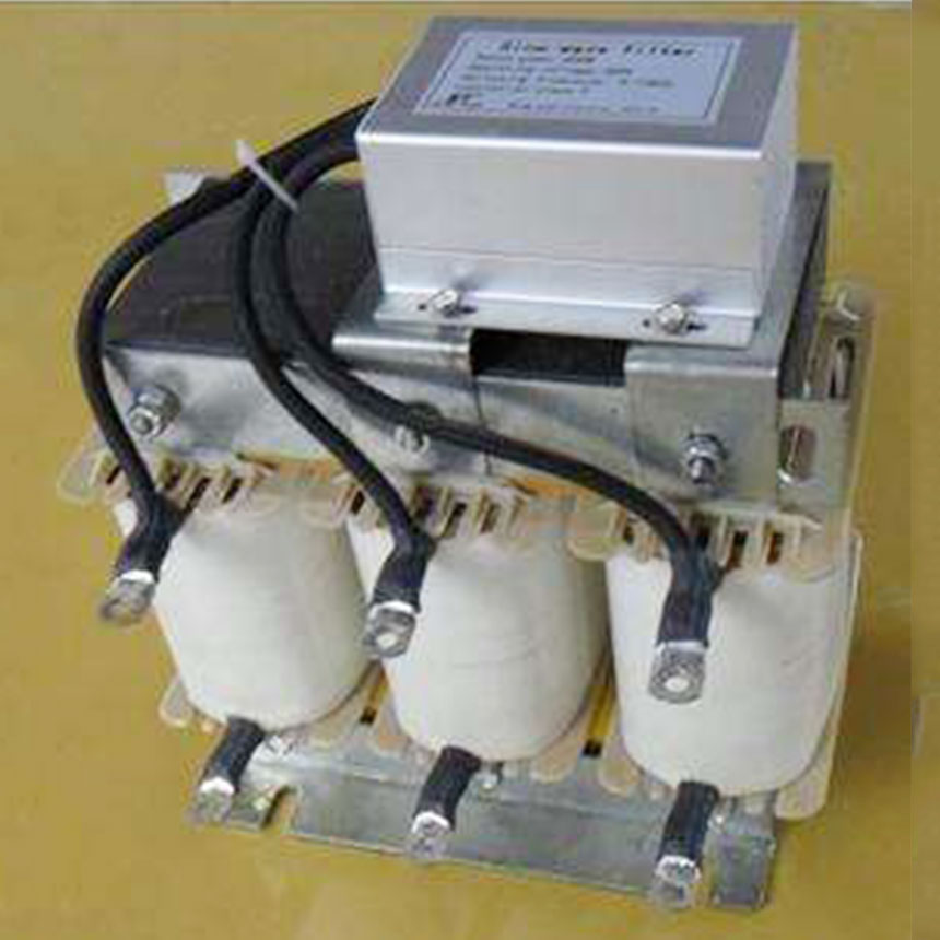
A dV/dT filter is a device that controls the voltage spikes generated by variable frequency drives (VFDs) and long motor lead lengths. This voltage spike event is generally known as the reflected wave phenomenon . This resulting reflected wave can cause very high voltages on the motor leads, which can lead to damage and premature failure of the motor winding insulation (even with inverter duty rated motors), particularly within the first few turns.
To control the effects of the reflected wave created by IGBTs in certain applications, a dV/dT filter will need to be applied. The design of a dV/dT filter is based on a number of factors, including IGBT switching time, load ampacity, cable length, and cable diameter. It is always best to use a dV/dT filter with an ampacity matched to the motor, and cable sizes (AWG) that are appropriate for the distance between the motor and the VFD while resisting the urge to oversize the cable. When an oversized cable must be used, upsizing the filter is an option if the lugs are not large enough for the cable. However, there is a risk when upsizing the filter too much; this is because the performance of the filter is reduced when the amperage of the filter is too large for the load. In these situations, it is advisable to add a terminal block at the dV/dT filter to step the cable down to the filter lug size. When applying a dV/dT filter, always remember to reduce the VFD carrier frequency to 2–4 kHz. Taking these factors into account will assist in the performance of the dV/dT filter in the application and the protection of the motor from dangerous reflected wave voltages up to 1000 feet from the VFD.
Working condition:
1. Working voltage: 220V/1140V
2. Working frequency: 50/60Hz
3. Rated current: 3A to 1600A
4. Carrier frequency: 2 to 8KHz,
5. Insulation class: Class F. H
6. Operation environment: No need derated suing during -10℃ to 45℃, if work in above 45℃, the rated current will be reduce 2% for every 1℃ rising.
7. Protection class: IP00-IP22.
8. Voltage drop: < 4%, if large than this value, the output torque of inverter will be lower.
9. overload tolerance capability: 1.5% rated current for 60s.
10. Noise: ≤65DB.
11. Temperature rise:≤85K
12: Dielectric strength: Steel wire core 3000VAC/50Hz/5mA/10s no electric arcing puncture.
13: Insulation resistor: 1000VDC insulation resistance value ≥100MΩ.
14: working under sea level below 2000m
15. Running condition: temperature-25℃ to 45℃, comparative moisture not over 90%.
16: No hazardous gas, no inflammable and explosive
17: Good ventilation.
dV/dT Filter Schematic


